There is an old saying… find something that you truly love to do, and you’ll never work a day in your life. Well, that looks nice on paper, but I don’t think it’s 100% accurate. No matter what you do for a living, love it or hate it, there are going to be good days and there are going to be bad days. If you love what you are doing, the good will substantially outnumber the bad. But there will always be the occasional turd floating in the toilet bowl to muck up the works. I bring this up because I have had the same job for 43 years, and I really love what I do. Even when I was dealing with chronic burnout, back in 2010, and found myself working on a commercial fishing boat, I decided to come back to being a machinist. To be honest, I have certain talents and skills and my job allows me to show them off. Certainly, if you’re good at something you’re going to show that talent off. It’s only human nature. And, if your job is hauling around fish guts, well, there just isn’t much there to show off.
On some days though, even with all that talent, the job is simply a job. Whether you’re not feeling well, you’re dealing with some outside distraction, or maybe it’s just the job itself. Whatever the reason, you just want to push through it and start the next day fresh. Perhaps it is the monotony of doing the same job, day in and day out, for over 40 years. Especially a job where there is a lot of repetition, like machine work. Then a day comes along where you’re handed a project that is actually challenging. Where you have to use experience that you have not tapped into for years. It’s those days that remind me why I decided to stick around.
I was recently handed just such a job. As with most jobs, the first thing I see is a blueprint like the one below. It’s an interesting part and creates a lot of manufacturing problems. As a machinist, that is what I like to see. I believe I said in my previous blog that a big part of being a machinist is being a problem solver. Someone hands you a blueprint like this and it’s your job to figure out how to take a piece of steel and turn it into what is pictured. First of all, let’s not call them problems. That’s much too negative. Let’s call these machining opportunities. There are three opportunities on this blueprint. First, how are we to hold the piece of material in order to cut that thread all the way across? Second, how are we going to locate this part so we can cut these notches to an accuracy of 1/2 of a degree? And finally, what exactly is a 2 T.P.I., double lead, straight, left hand, Acme thread with a blunt start? I mean what is it besides a mouthful?
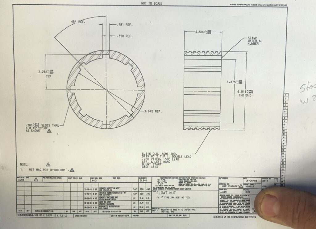
Let’s take the questions in reverse order as the last one is really the easiest one to answer. As an oilfield machine shop, we cut threads all day long. As a consumer, if you were to go into the local hardware store and ask for a 3/8-16 by 1-inch long allen head cap screw the clerk is going to know exactly what you need and he’s going to supply it. This is because common nuts and bolts are all standardized throughout the country. And indeed, throughout the world if you decide to go metric. Ask the clerk at the hardware store for this particular thread and you’re likely to get nothing more than a blank stare. That’s because this is not a standard thread found in anybody’s book of nuts and bolts. It is unique to whatever part it is mating, and you are not going to go someplace and find hundreds of these to choose from. It’s what we refer to as a one off. So, let’s break it down First, there is the 6.516-inch O.D. This is nothing more than the outside diameter measurement taken at the top, or what we refer to as, the crest of the thread. Going back to that 3/8 allen head cap screw, you will find that the 3/8″ measurement is the outside dimension of that screw.
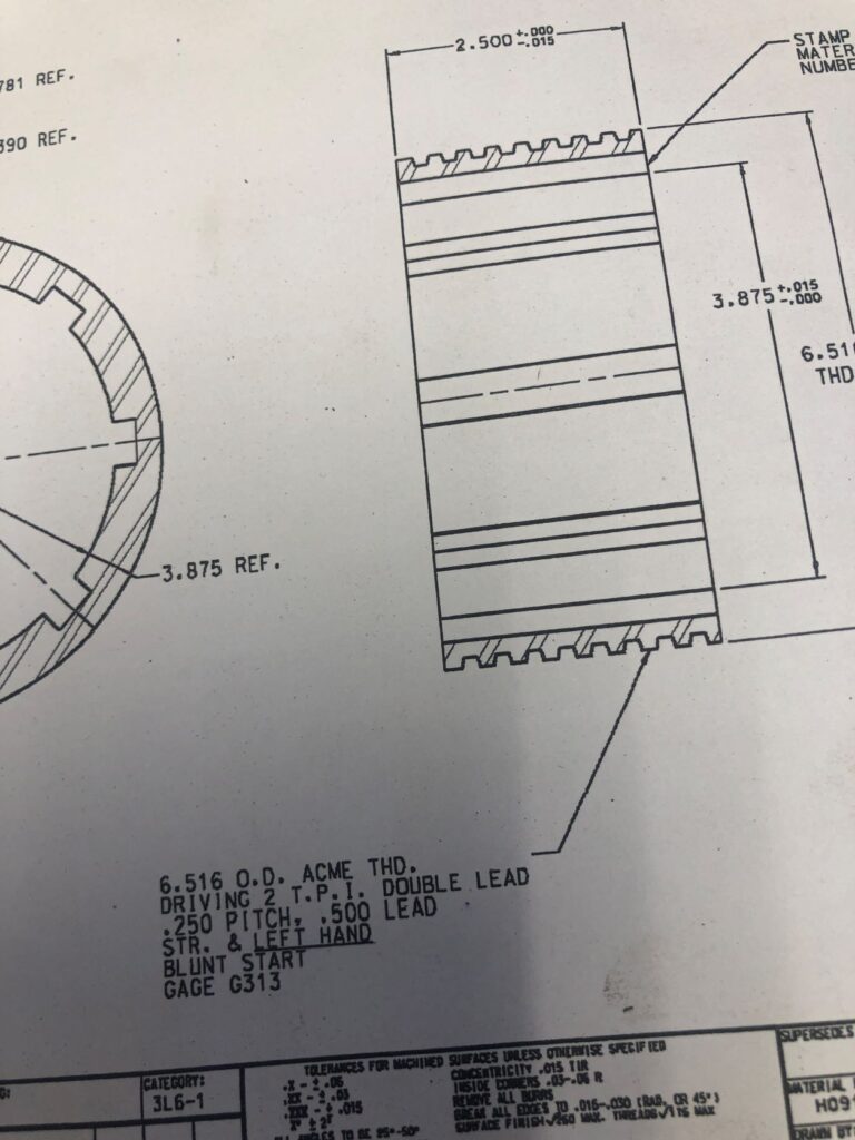
Next it calls out an Acme thd. driving. Acme refers to the thread form and thd. is a lazy way of saying thread. At a glance, the profile of an Acme thread looks square but, upon closer examination, you will notice that the sides of the thread have a slight angle. Acme threads are known as power threads, so the part that says driving is a bit redundant. The next callout, 2 T.P.I. means two Threads Per Inch, which becomes important later on in this exercise. It means if you take a measurement from the middle of the crest of one thread and move over one inch there will be two threads. This is a very coarse thread but not uncommon in the industry and we even cut a very similar thread for another customer. Double lead is where it gets a little interesting. If you look at any standard thread it is simply a spiral wrapped around a piece of material with one starting point. A double lead thread looks the same, but it actually has two starting points located 180 degrees opposite one another. The advantage here, is you can screw onto and unscrew from the mating part twice as fast. The best example I can think of is, next time you have a big jug of Simply Orange juice look at that thread on the cap. They actually use a triple lead thread which is why you can screw that cap back on nice and tight with only about a one quarter turn. They also make really good juice. Next, we have a line that caused some problems, .250 pitch, .500 lead. In a typical, single start thread, the pitch and the lead will be the same. Because this is a 2-pitch thread, the lead will be twice the pitch. For a 3-pitch thread, think Simply Orange, the lead will be three times the pitch. Str. & left hand means that the thread is straight and is a left-hand thread. Straight, because in the oil field a lot of threaded connections are cut on a taper so it’s important to know that this was not a tapered thread. Everybody is familiar with the old saying, righty tighty, lefty loosey, meaning you turn to the right to make your thread up tight, and you turn to the left to make it loose. A left-hand thread is the opposite, and it doesn’t rhyme. It just means that in order to make up the thread you will be turning to the left and not the right. A blunt start means they want that lead, or starting thread machined back. Most threads have a slight chamfer on the end and, as a thread runs out, it gets thinner. In this case, this is a very coarse thread and they do not want the chamfer. They want that lead thread ground back a little bit, so it has some meat behind it. The last item indicates Gage G313. That would be the gauge we would use to check that thread but unfortunately, they did not have one. It was up to us to make sure we hit all of our numbers so that when they screwed this onto their mating part it would make up properly. That was probably their biggest mistake, but we will get into that later.
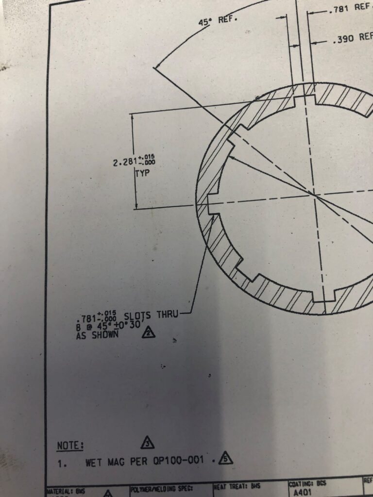
Next, let’s look up the call out for the eight slots. I am guessing this part is designed to slide over some type of spline which will locate on these slots. Cutting the slots is an operation called broaching and is somewhat specialized. Not all machine shops will have a broaching machine. Fortunately, we do. Unfortunately, it is probably 70 years old if it’s a day. But we both work, and it doesn’t take nearly as many pee breaks as I do. We are okay on the width, as we have a tolerance of +.015”. In machine terms that’s a mile. The width, 0.781”, is not a standard size so we had four of our 7/8″ broaches ground to the proper width. If you look elsewhere on the drawing, you will see we have the same tolerance for the depth of the slot, again, an easy tolerance to hold. The tricky part is going to maintain that location of plus or minus 0-30’, which is half a degree, with any accuracy.
After spending a restless night thinking about it, and then doing some online research, I came up with a solution. We needed what is commonly known as an index, a jig or a fixture which would allow me to accurately move from position to position and even come back to any of my previous positions without losing my location. I started by machining a steel ring to the same outside diameter as the float nut. I bored the inside diameter of that ring to 1/16” larger than the diameter of the slots, or 4.625”. Next, I machine the uneven face of the material so that it has a clean, machined surface perpendicular to the OD and ID of the material. While still holding the stock in the chuck of my lathe, I used a special tool to part the ring off at 1/2 inch in length, thus ensuring that both sides would remain parallel. Now, I took the steel ring over to our mill and drilled a 3/8” hole completely through the ring at a distance of 5.700” from the center line. Using a soft brass hammer, I gently tapped a 3/8” pin into that hole as it was a tight fit, which is what I wanted. I left the pin sticking out of the plate about 3/8”. On the broaching table, there is a ‘V’ shaped backstop that we push our material up against in order to locate and hold it in position, centered to the broaching tool. I pushed my indexing plate up against that backstop with the pin offset at about 45 degrees, just to keep it out of the way of my work. In reality, I could have rotated the index plate and located that pin just about anywhere I wanted it. I wanted it at 45 degrees. As a final addition to my index fixture, I cut two pieces of 1-1/2” wide by ¼” thick flat bar stock about 4” long. I ground a slight radius into one end of each so that it neatly butted up against my ring. I then positioned one of these on each side of the ring, parallel to my line of sight. I showed my welder what I had going on and he took the ring and the two pieces of flat stock, positioning them the same way on his welding table, and welded the two pieces of flat stock to the ring.
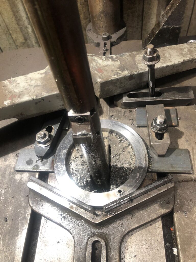
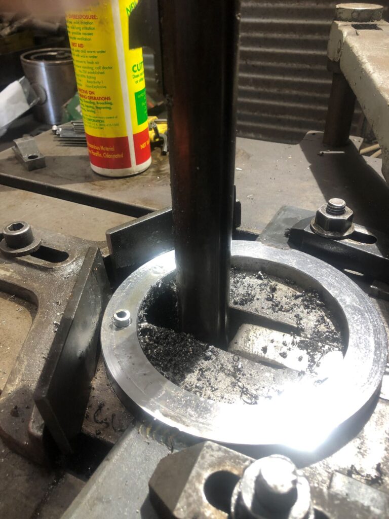
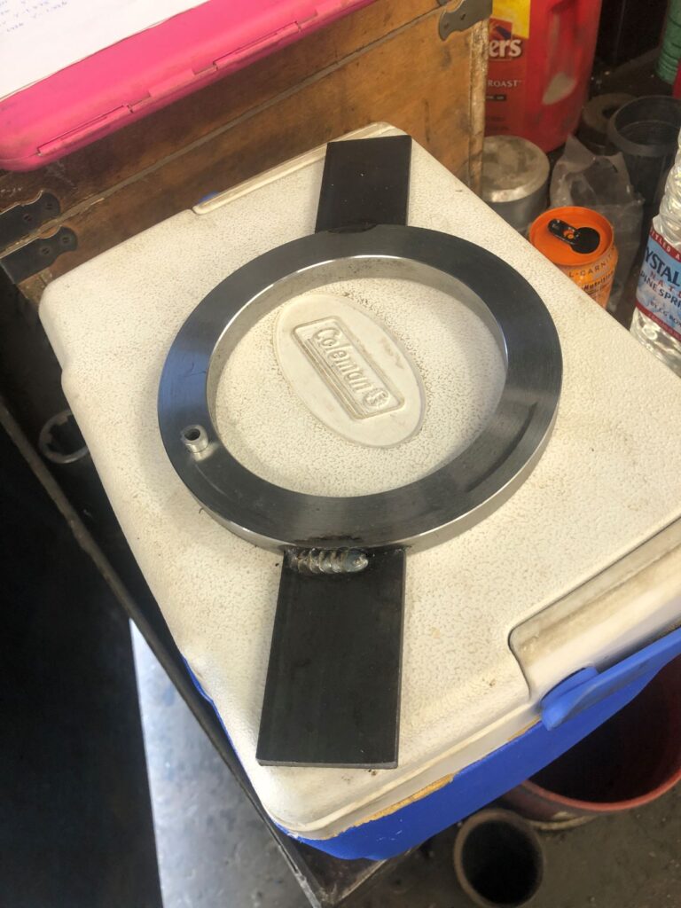
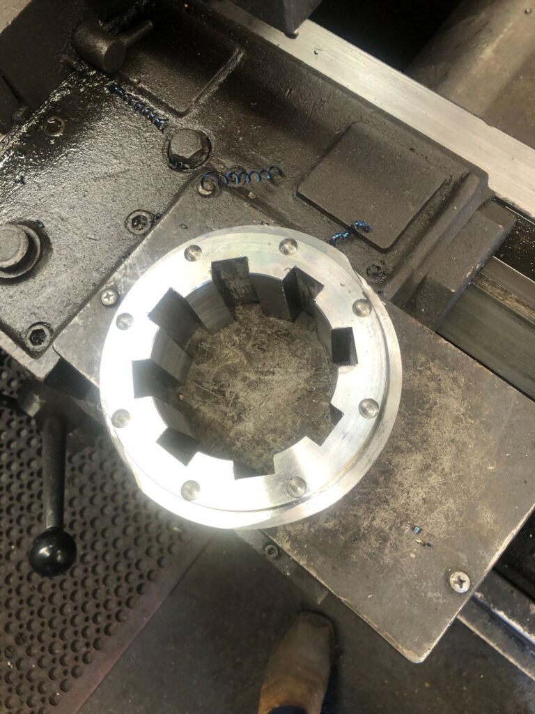
We brought the completed jig back to the table and located it firmly in the notch of the ‘V’ shaped back stop. The table has mounting slots in it on each side of the broaching bar. I placed a key in each slot and used some clamps to lock the whole thing to the table, as you can see in the photograph. First problem solved.
Now we need to check on our actual piece. The blueprint calls for 4130 or 4145 steel. We made it out of 4145 simply because it was what we had available in the yard in the proper size. Either one of these is very hard steel and difficult to machine. The piece of stock that we used was about eight inches long. This allowed us to chuck up on a good four inches of material with the remaining four inches sticking out of the spindle. The spindle, by the way, is the part that rotates. In a lathe set up we hold the material in the spindle, and it rotates while the tooling remains constant. In a mill set up we clamp the work to the table where it remains constant while the tooling rotates in the spindle. There was a guy that worked for us named Hector, since retired. Whenever we were training someone new in the machine shop Hector got to train him. Now Hector liked to work very quickly, and he liked to work up close to the chuck. That’s good because these threads have a tendency to vibrate and the closer you are to the chuck the less likely you will have a vibration issue. We had quite a number of machinist candidates walk away from the job after spending a day or two with Hector. The idea of working that fast and that close to the chuck just scared them because they worried about crashing into the chuck. IT HAPPENS! It’s probably just as well. I’ve always told someone that is just starting out not to be afraid of the machine. If you are afraid, you are in an accident waiting to happen. And when that accident happens, you are more than likely to panic, making the situation worse. Respect the machine. You will probably get hurt at some time in your career if you work long enough. In 43 years, I’ve been to the ER six times, which is about average. If you have a healthy respect for the machine, you can react in a way that will prevent a minor injury from becoming a major injury. I’m happy to say that I still have all my fingers, both eyes, and the worst that has ever happened is I needed to get a couple of stitches.
Back to our project. We face the end of material, which was saw cut, so it is square. Next, we bore the inside to our call out diameter of 3.875 inches.
We machine our outside diameter to the 6.516 inch call out. Now we cut a groove behind the part, starting at the 2-1/2-inch mark and extending about ¾” wide, with a diameter of 6.015 inches. This is the theoretical diameter of the thread at its root, or deepest part. You won’t find that on the drawing, but Acme threads are standardized and are cut to specific depths depending on the number of threads per inch. A 2-pitch Acme thread has a specified depth of ¼” or .250”, meaning the diameter at the root will be 6.015 inches. Thread cutting on a lathe is done on a lead screw. A slowly (usually) rotating dial has different positions indicated, typically by a series of lines and numbers. When cutting this thread, you position the threading insert somewhere in the ¾” wide groove at a depth of .010 inches. The nice thing about cutting a left-hand thread is, when engaging the thread gear, you are moving away from the chuck. You watch the dial and, if you are going in on numbers, when any of the numbers lines up with an indicator notch, you push a handle down. This engages the leadscrew, causing the tool to move across the surface of the part, cutting a spiral groove. Once no longer cutting, dial out and away from the part, go back to the starting position, dial in .010” deeper, and repeat the process. Continue repeating this process until reaching the final .250-inch depth of the thread. Most of the time, aside from some deburring, the thread would be complete at this point. But this is a double lead thread, and even an amateur could look at it and see that something wasn’t quite right. Now we go in on the lines between the numbers, which splits the thread, and gives us a second lead thread, located 180 degrees opposite the starting point of the first thread. Follow the exact same process, except now go in on the lines between the numbers until reaching the full depth of the thread and it looks something like the thread in the video.
Once the thread is cut and cleaned of any sharp edges, we want to use our special parting tool and part the piece off from the stock being held in the chuck. But, and this is very important, part off the material at a length of 3.00”, a good half inch longer than the call out on the print. From here we take the part over to our mill and clamp it to the mill table with the end that we just parted facing up. There is a whole process to finding the center line of our part, which I won’t go into here. Once we have found that center line, though, we can go into our CNC program and drill what is known as a canned cycle. This is simply a way of telling the mill that we are doing something very specific. In this case we want to drill a bolt circle 5.7 inches in diameter, consisting of eight holes, each .450” deep, with a hole size of .377”. We feed these parameters into the program, and it automatically calculates the location of each hole from the centerline. Note that the holes are .450” deep. This is deeper than the locating pin on our fixture, which sits up 3/8”, and it is also shallower than the extra half inch of material that we have added to the part when we parted it from our stock in the lathe. They also measure .377” in diameter, which is just slightly larger than the locating pin in our jig. We want to be able to set the part onto the locating pin and remove it without raising our voice.
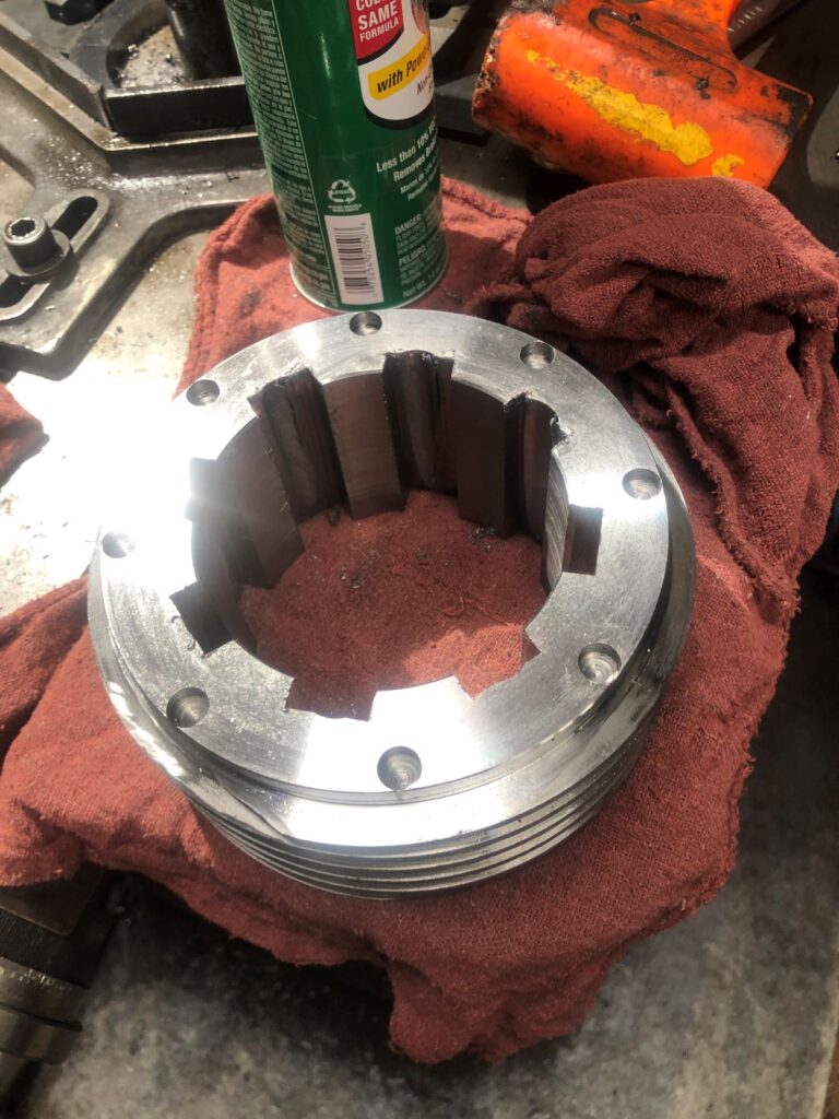
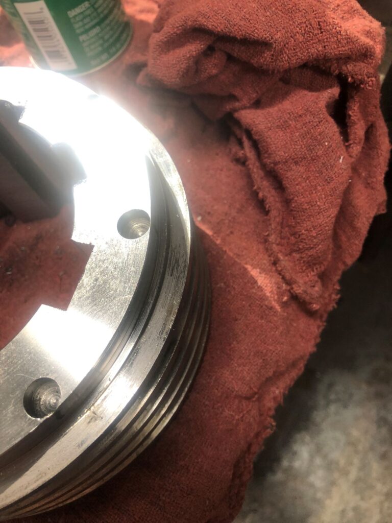
I decided to perform one other operation before actually broaching the slots. I did take the part over to the broaching machine and position it on the locating pin of my jig. With the machine off, I then hand dialed everything into position for the very first cut. I eyeballed the centerline of my broaching insert and scribed a line on the part. This may seem like an inaccurate way to do it but I had .031” in tolerance which is more than enough to eyeball something in. I can usually eyeball a part in to about .015”. I then went back to my trusty CNC mill and clamped the part to the mill table again, this time on a couple of ½” risers. After locating the center line, I input the parameters for another bolt circle, although that’s not what I was actually drilling. I used a ¾” endmill with 3-1/4 inches in length coming out of the spindle. The slots we were cutting were .781” wide. (That’s my .031” in tolerance). They were also .343” deep. That is a lot of very hard material to remove in a broaching process. To cut back on wear and tear, I programmed this bolt circle so that the endmill would come down about .310” deep and, if I was accurately centered, I would have .015” of excess material on each side. The idea being to remove as much material before I actually started the broaching process.
Now I was ready for the broaching process. With my jig locked to the table, I seat one of the locating holes drilled into our part onto the locating pin. I make sure the part is pushed up snugly against the backstop. There is a long clamping arm that clamps our part onto the broaching table as seen in picture and video. The broaching machine is designed such that, with every stroke, it automatically feeds the table two or three thousandths into the blade. As small as this is, 4145 steel is such hard material that, after every stroke, I would disengage it, allowing it to make two or three passes at the same number before going on to the next location. Even with that precaution, I was feeding the broach in to just past where I had milled out the stock, meaning I still had another .020” to .030” inches to take out. But with each new slot I was seeing a little more taper where the blade, as it was becoming dull, was pushing away from the material. After four slots I replaced the broach and ran the other four slots. After the next four slots were roughed in, I replaced the broach again, now on our third blade if you are counting. I started to take the slots to their final depth. I managed to get six of them done this way before swapping out for the fourth, and last, blade for the final two slots. Even so, they all had a slight bit of taper, but this was an easy fix. I loosened both of the clamps and removed my jig, which I no longer needed, from the table. Turning the part over I lined it up against the backstop and, with the machine off, brought the blade into the slot. I then clamped the work to the table knowing that everything was aligned. Working my way around the part, I broached all eight slots from the bottom side, taking out all of the taper.
There was just one last thing to do. The part was still slightly over half an inch too long with a bolt circle pattern that had to go away. I put it back in the lathe, chucking it with some shim stock to protect the threads, and faced off the part until it was the proper length. In the process the locator holes I had drilled were removed as if they had never existed.
There is a great irony here. The photograph on the left is the part that I made. The photograph on the right is a sample part they sent over after the fact. Notice a difference the threads? This is actually the thread that they wanted.
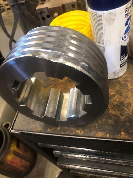
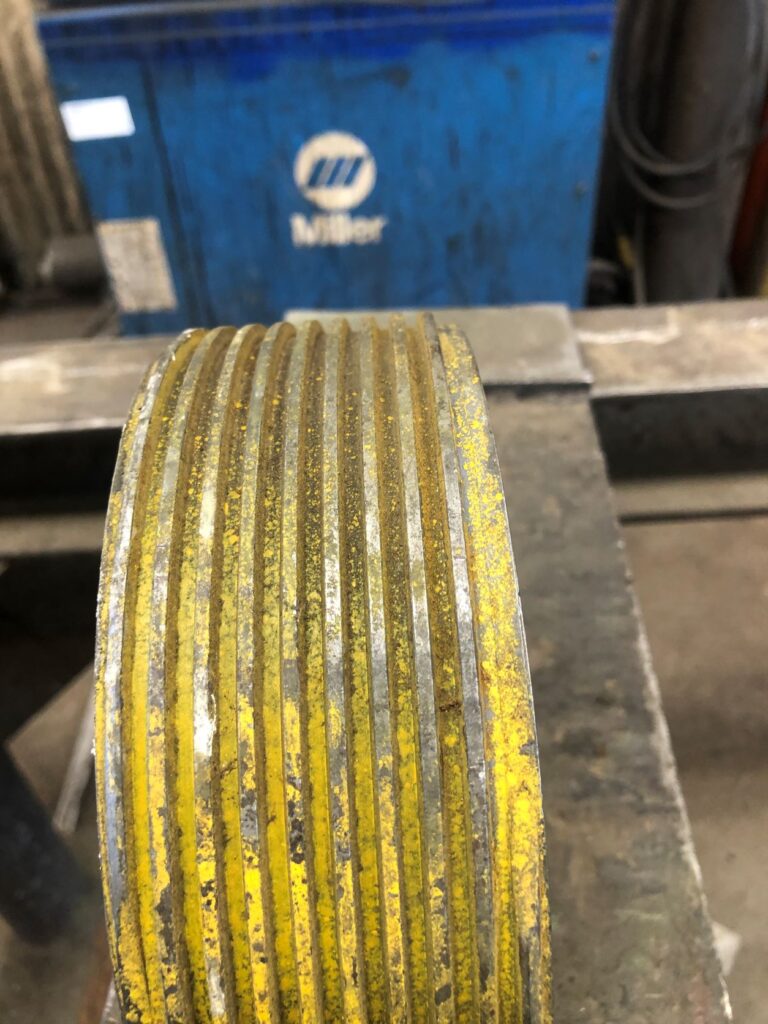
If you go back to the original call out on the blueprint, they describe the thread as 2 T.P.I. double lead. By definition there will be two threads for every inch. On the next line they call out .250 pitch, .500 lead. The .250 is the distance between crests, which means in one inch there will be four crests. That is 4 T.P.I. So, the problem was the blueprint described two different threads. As I said, we cut a similar thread for another customer, and we have always referred to it as a 2-pitch double lead thread. When I saw that notation on the blueprint, I focused on that and, unfortunately, disregarded the information on the next line. In this case, the customer admitted the mistake and the blueprint was confusing. They also admitted they should have supplied us with a gauge or, at least, a sample of the thread form so that we knew what we were cutting. This is actually something of a problem in my industry. It’s a lack of standardization. We make tools for different companies and a lot of the tools are similar if not exactly the same. If it’s a regular customer and a tool that we do a lot of repeat work on, we rarely see a blueprint. We have made the tool so many times we can practically do it in our sleep. But one company will call the tool by one name while another company will refer to it by another, even though they are exactly the same. In this case, because it was a tool we had not made before and were unfamiliar with, we did receive a blueprint, albeit one with misleading information. Fortunately, through long association, we are generally on the same page with our customers, no matter what they call the tool. And, when in doubt, we ask questions. In this case, the customer took responsibility for the error and agreed to pay for the tool. They sent us a sample (pictured) which is the same tool except the thread diameter is about one inch larger. They asked us to simply machine the piece down to the proper diameter and cut A 4-PITCH DOUBLE LEAD LEFT HAND THREAD.
I know this one was kind of long and I hope I didn’t bore you too much. It is always my greatest wish that you learn something along the way with these blogs. I tried to dumb this down and not get too technical, but I imagine a lot of you probably still didn’t have the patience to read it all the way through. Sometimes though, it’s just nice to step back and remember why you do what you do for a living. If you have been doing your job for a while, I hope it was worth sticking around. Next week, unless something else catches my interest, I’ve got a little food blog in which I share a great place to have breakfast in Bakersfield.
I have been watching information concerning the WonderCon in Anaheim, scheduled the first weekend in April after a two-hear, COVID induced hiatus. Sadly, I’ve seen nothing to confirm the dates. I also have a special blog about a property we’re getting ready to sell which is a great example of what you can do right with a property as well as what you can do wrong. It’s a great example of both. I was going to attend some spring training games and blog about that but MLB has already started canceling spring training games due to the strike. We’ll just have to sit back and wait to see what happens. But even if Major League Baseball isn’t, I encourage you to always swing for the fences.
